


Guidewires were initially invented and used by Dotter and Judkins to cross a disease segment of the artery for further intervention. However, the initial wire used for coronary intervention was a spring coil guidewire over which a series of large rigid dilators were advanced.
Andreas Grüentzig replaced these dilators with inflatable balloons, which were introduced percutaneously, hence pioneering the era of percutaneous coronary angioplasty. After Grüentzig pioneered the first angioplasty, a group of cardiologists met and formed a registry under The National Heart, Lung, and Blood Institute. Since then, significant improvement in different types of equipment and techniques were made.
The original dilatation catheter with a short tip of guidewire could not be modified once the catheter was introduced, providing the operator with no control to maneuver the catheter/wire inside the vessel. In 1981, Dr. Simpson developed a new catheter system with an independently steerable guidewire located in the balloon catheter’s central lumen, replacing the short fixed non-steerable wire tip (5 mm) manufactured by Andreas Grüntzig.1 The introduction of the coaxial steerable guidewire was the first revolution in the history of coronary angioplasty.
Compared to the early version of guidewires, modern guidewires are designed to combine tip softness, trackability around curves, and precise torque control, which allow the guidewire to be steered through tortuous vessels and side branches.
a) Wire Basics
The first step to understanding how to use a guidewire is to know the engineering aspects of wire technology, core material, and how different components change the wire’s characteristics. Guidewires are comprised of mainly four features: core, tip, body, and coating. The small variations in these components have drastic impacts on guidewire characteristics and their intended application. The areas that differentiate over a hundred guidewire are mainly due to various compositions at the wire’s distal end.
Guidewire Components

PTFE = polytetrafluoroethylene
- Core: It is the stiffest and innermost part of the wire. It provides stability and steerability and extends through the wire’s shaft from the proximal to the distal portion where it tapers.
- Core Material: The core is usually made of stainless steel, which provides excellent support with excellent torque transmission but is less flexible and not kink resistant. On the other hand, nitinol core, a super-elastic alloy of nickel and titanium, has more flexibility, excellent resiliency, and kink resistance. Newer wires (hybrid type) are made of stainless steel and nitinol distal tip for better torque transmission and excellent flexibility with kink resistance. (i.e., Runthrough, Minamo, Maestro, Spectre)

Nitinol


- Core Diameter: It is the part of the wire that tapers to the tip, not the wire’s overall size, and determines the flexibility (smaller diameter) and support (larger diameters).


- Core Taper: This is the part of the wire that extends from the core to the tip. The ability to transmit torque depends on the taper’s length; shorter tapers tend to prolapse but provide more support, while longer tapers offer less support but track successfully.


- Tip: It is the distal tip of the wire. Various tip designs could affect the steerability of the wire.
- Core to Tip: Core extends to the tip of the wire. This design provides precise tip control and increases the wire’s diameter, enhancing the wire’s stiffness to help cross-resistant lesions.

- Shaping Ribbon: Core does not reach the distal tip of the wire but is wrapped in a ribbon of flexible metal to make the tip more flexible, atraumatic, and allows shape retention.

- Composite Core (CC) or Inner Coil Technology (ICT): Composite core (Dual Core and Dual coil) is made of multiple wire components to enhance durability and 1:1 torque transmission. The distal part of the composite core wire consists of core and twist wires, whereas the proximal portion of the wire is composed of rope coil, twist, and core wires.
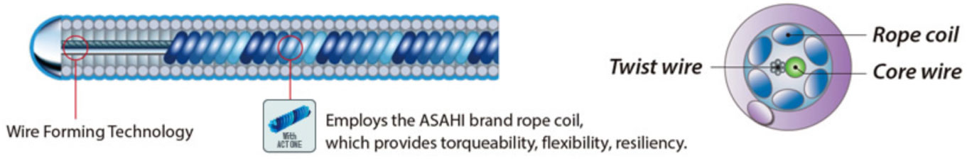
Composite Core (Asahi)
- Excellent Torque Transmission
- Wire protection for durability
- Allow smaller, more flexible core
- Provide excellent tip durability
Inner coil technology is composed of a stainless steel inner coil affixed directly to the distal portion of the stainless steel core enhances the shape retention and durability of the distal tip, reduces whipping, and provides exceptional torquability.
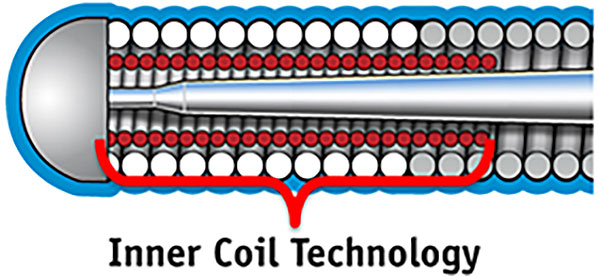
Inner Coil Technology (Boston Scientific)
- Body (Coil, Cover, and Sleeve): The body of the wire surrounding the core is usually made up of coils or polymers (plastic). Coils help maintain constant diameter, torque control, and tactile feedback. Various coil forming technologies have evolved in the contemporary era. Weaving multiple small wires into a coil is the most popular one, resulting in increased strength and a better torquability and torque response than a single coil.
XTRAND Coil technology, used in Gaia Next series, is multiple wires braided together to create a coil, and the design avoids coil stretching, and its anti-trapping feature avoids coil damage.
Single Coil

XTRAND Coil


A polymer can either cover the distal spring coils or the core itself, providing a smoother surface for tracing tortuous vessels. A wire with both a polymer jacket and hydrophilic coating has an approximately 70% reduction in wire surface resistance when compared to an exposed coil and hydrophilic coating.
Hybrid wires, sometimes called sleeved wires, consists of a polymer cover on the body while leaving the distal spring coils at the tip uncovered.


Outer Coil ONLY

Tip Coil ONLY
Various Guidewire Construction based on different form of coils and Covers
Full Spring Coil Tip: Spring coil covering the distal core provides tip resiliency and tactile feedback.
Polymer Jacket over the Spring Coil: A wire with a polymer jacket covering over the spring coil: spring coil promotes tip resiliency while polymer jacket enhances crossability and smooth device tracking.


- Coating: The wire body is coated by an overlay, a specific material that can reduce the surface friction and improve device interaction and guidewire tracking.
- Hydrophilic coating attracts water to create a slippery ‘gel-like’ surface when wet and non-slippery when dry. It reduces friction, increases lubricity of the wire that enhances tracking and crossing, although, on occasion, could unintentionally go into false subintimal spaces with increased risk of causing perforation.
- Hydrophobic wires are usually made of silicone and repel water to create a ‘wax-like’ surface, enhancing tactile feedback but decreasing slipperiness and trackability.
- Hybrid wire combines the hydrophobic tip for better tactile feedback with hydrophilic coating for smooth device delivery. In the contemporary era, the vast majority of guidewires have a hydrophilic coating. Put simply, hydrophilic wires increase lubricity, and hydrophobic wires increase tactile feedback.
- There are many proprietary coatings available in the market (e.g., M-Coat, Hydro-Track, or Slip-Coat (Asahi), etc.)

Terminology of different wires’ parts
Coil Length: The spring coil length can vary significantly from as low as 2.2cm upwards to 30cm. Generally, shorter coils are found on devices intended for high support and longer coils on trackability and flexibility devices.
Radiopaque length: The distal tip, an opaque part under x-rays, is usually about 30mm in length except for specialized CTO wires. It helps to make a measurement of the diseased segment and makes it easier to locate the wire. Some specialty wires have multiple radiopaque segments, such as the Medtronic Zinger Marker and Boston Scientific Forte Support Marker for more accurate measurements.
- Torquability: It is an ability to transmit rotating elements applied on the proximal end of the wire (outside of the guiding catheter) to the tip of the wire. It is the crucial determinant of the operator’s ability to steer the wire through the vessel precisely. An ideal wire should provide a 1:1 torque, which can be affected by core composition, tip stiffness, and surface coating.
- Flexibility: Ability of the wire to flex on its longitudinal axis while maintaining its trackability and torquability. It is the critical determinant of the tip strength. Flexible wires are soft and generally atraumatic. A wire’s flexibility can be labeled extra floppy/light, floppy/soft, and stiff.
- Shapeability: The ability to modify the guidewire’s distal tip before the procedure to access difficult anatomies or perform intentional drilling through a CTO.
- Shape Retention: A wire’s ability to retain an intended shape after being exposed to deformation and stress. Different strategies improve shape retention, including Asahi’s composite core, which uses an additional coil and wire inside.
- Nitinol wires such as Terumo’s Runthrough, as an inherent characteristic of the metal, have better shape retention than stainless steel.
- Tactile Feedback: Any physical sensation felt through the wire’s proximal end during wire advancement inside the coronary artery. Hydrophobic coatings offer the best feedback, but such wires advance with more difficulty than slippery hydrophilic wires. An additional polymer sleeve could further reduce feedback.
Trackability or deliverability or crossing: It is an ability to follow the tip and advance smoothly along the vessel through stenosis or occlusion. Trackability is improved by nitinol core material and longer taper length, hydrophilic coatings, and polymer sleeves. Below, an Asahi Sion Black and conventional guidewire are advanced into an artificial vessel. Additionally, a comparison of guidewire surface roughness in a jacketed wire vs. spring coil wire is illustrated.


- Tip Load: Tip load can be determined by advancing the wire into a standard surface until it deflects the tip, at 2mm from the tip. A high tip load can help when crossing a resistant or highly stenotic lesion, while a low tip load makes the tip very soft and atraumatic. Tip load is predominantly determined by core material and thickness, with stainless steel core-to-tip style used for the highest tip loads.

- Support: It is a measure of a guidewire’s resistance to a bending force. A more supportive wire can aid in device delivery and vessel straightening, while a less supportive one could assist in accessing tortuous anatomy. Support and propensity for wire prolapse are directly related.
- Whip: A smooth torque input from the operator results in a sudden jerk at the wire’s distal end. This effect can be minimized through hydrophilic coatings and polymer covers/sleeves. In the chart below, the dotted line shows a whip response plotted. The y = x line demonstrates an ideal guidewire with a 1:1 torque response contrasted with the erratic whip visualized by the dotted line.

Characteristics and Functionality of the Guidewires
Knowing the properties of guidewire and the specifics of the different types are crucial in selecting appropriate guidewire. However, it is strongly recommended to choose and master only a few wires instead of having superficial knowledge about multiple wires.
- Wire tip configuration and manipulation
The majority of guidewires are straight tipped and can be modified/shaped according to the vessel contour. The tip can be shaped with either the introducer needle or the shaping needle that comes along with the wire. Usually, a simple J shaped curve at the wire’s distal end will help track the wire through the vessel. The wire should be advanced gently through the stenosed segment. Forceful pushing of the wire can result in plaque disruption, leading to acute thrombus formation and occlusion of the vessel. It is recommended that 180-degree clockwise or counterclockwise rotations of the wire should be performed during advancement in order to avoid wire advancement into smaller branches.5 However, 360-degree rotations should be avoided, particularly when a second wire is required to prevent entanglement.
The wire tip should be placed as distal as possible, so the wire’s stiff part is across the lesion, providing adequate support to advance interventional devices.
- Tip to wire specific blood vessel (LAD, LCx, RCA)
- Left anterior descending (LAD)
The left anterior oblique (LAO) caudal view is the best initial view to wire the LAD. Once the wire position is confirmed in the proximal LAD, further advancement into the mid and distal LAD should be carried out in the right anterior oblique (RAO) cranial view.
- Left Circumflex (LCx)
A broader tip helps with entry into the LCx, and a smaller curve supports advancement into the Obtuse marginal (OM).
- Right Coronary Artery (RCA)
If the RCA’s origin is relatively normal, a conventional soft wire with good steerability to avoid side branches is chosen first.

- Desirable Wire Characteristics
- Non-CTO guidewire selection
- Simple/Uncomplicated Lesion
- To treat simple, concentric stenosis of the artery, the vital element of the wire is safety.
- As these wires are not required to go through difficult or extreme anatomies, unique properties are not required.
- The wire should have an atraumatic tip, good torquability, and favorable trackability with a spring coiled nitinol wire.
- The choice of wires can include Runthrough, Balance MiddleWeight, and Sion Blue.
- Tortuous Vessel
- In dealing with tortuous anatomy, the workhorse wires aren’t designed to tackle this challenging lesion and often fail to navigate through the lesion.
- The presence of wire’s flexibility, lubricity, and excellent trackability is essential to tackle this challenging anatomy.
- The optimal wire should have a soft tip, polymer/hydrophilic cover, moderate support, or a hybrid type with a hydrophilic body and hydrophobic distal tip.
- The choice of wires can include Fielder, Whisper, Pilot 50 and CHOICE Floppy.
- Calcified Lesion
- Two distinct components are involved in wiring a calcific lesion: 1) crossing the lesion and 2) delivering the devices.
- The ideal wire to cross a heavy calcified lesion should have a soft tip with polymer/hydrophilic cover or a hybrid type of wire (hydrophobic tip and hydrophilic body). The wire choice can be Runthrough, Fielder, Whisper, and Pilot 50.
- To deliver PCI devices through a calcified lesion, the wire’s crucial characteristics include high support, good tactile feedback, and excellent torquability/trackability.
- The wires selection include Iron Man, Mailman, Hi-Torque Balance HeavyWeight, the Hi-Torque All-Star, or the CHOICE Extra Support with the buddy wire technique.
- Bifurcation Lesion
- The guidewire properties to tackle a bifurcation lesion should include slipperiness, excellent trackability, and slightly stronger tip load. It is paramount not to choose those with a higher risk of wire retrieval damage (e.g., non-polymer-coated wires) as the wire might be jailed during the procedure.9
- The choice of wires for bifurcation intervention can include a workhorse wire (Runthrough, BMW, CHOICE Floppy) in the main branch and polymer-coated wire in the jailed side branch (Fielder, Pilot 50, Whisper MS).
- Occasionally, an aggressive wire with more tip stiffness (Gaia 2 or MiracleBros 3) along with a microcatheter may be required to enter the side branch in a challenging case.
- Thrombotic Occlusion
- In a setting of an acute thrombotic lesion, the wire shouldn’t have significant resistance while traversing a lesion.
- The main objective is to cross the occlusion and advance the wire to the distal lumen softly and atraumatically.
- A soft wire would be the choice rather than a stiffer one with the hydrophilic or coated property. The operator can use any workhorse wire in this situation.
- In subacute occlusions, the thrombus material could have become more organized and may require a stiffer tip and higher tip load to facilitate in crossing the lesion. The wires choice can be Fielder, Gaia series, and MiracleBros 3.
- Angulated Lesion
- The wire properties to navigate the angulated lesion is torquability, trackability, and wire flexibility. The ideal wire would be a soft tip with polymer jacketd and hydrophilic cover.
- Our choice of wires are Fielder, Whisper, and Pilot 50.
- However, we may require a stiffer tip with hydrophobic coating at the tip to have a better tactile feedback with torquability such as MiracleBros and Provia.
- Sometimes, we may require additional devices (i.e., angulated microcatheter or dual lumen catheter) to navigate an angulated lesion or when re-crossing a jailed side branch.
Polymer Jacket
Non-Polymer Jacket
Externalization Wires
Wiggle Wire
Extra Support Wires
- Strategies of CTO-PCI (Algorithm)
There is no single guidewire that can be universally used in all CTO lesions and all possible circumstances. Familiarity with various CTO guidewires, proper selection based on angiographic features, and proper wiring techniques are necessary for CTO PCI success.

CART = controlled antegrade and retrograde subintimal tracking; RWE = retrograde wire escalation 5-7
Wire Selection in CTO-PCI
Essential features to consider when selecting a guidewire include 1) tapered tip or not; 2) tip load and stiffness; 3) coated or non-coated polymer; 4) trackability.
- Antegrade Approach
Although multiple guidewires can be used in the CTO intervention, the principle on how to choose the wire is mostly unchanged.
- For a focal lesion (<10–20 mm length), tapered, straight CTO without a side branch, the first choice is a soft, tapered, polymer-coated wire for initial (micro) channel tracking.
- However, it is essential to be aware that wire manipulation is often tricky, and linear force transmission can be attenuated.
- Antegrade wire escalation (AWE) is mostly recommended in the antegrade approach by penetration or drilling.
- When a wire passes the proximal cap of CTO, it is advisable to exchange the wire for a softer, steerable wire to minimize any inadvertent damage (expansion of subintimal space), called wire step down or escalation-deescalation.
- The parallel wiring method can be used under the antegrade approach. When the first wire fails to enter the true distal lumen, the second wire (tapered and stiffer wire) is advanced, while the first one can be used as a road map, thereby avoid entering into the subintimal space created by the first wire.
Our choice of wires for Antegrade Wire Escalation (AWE) (Stepwise approach) includes:
- Fielder (Non tapered polymer jacket tip), Fielder XT/XT-A/XT-R (Tapered polymer jacket tip)
- MiracleBros (Open Coil, Straight tip, high tip stiffness > facilitates drilling and can create a curve) or Gaia/Gaia Next series (Tapered, hydrophilic coating, composite core with 1:1 torque, high tip stiffness)
- Confianza 9/12 (Tapered, hydrophilic coating, high tip stiffness)
Wire for microchannel tracking:
- Fielder, Fielder XT, Fielder XT-A
- Gaia/Gaia Next series
- High Torque Pilot 50/150
Wire for Drilling:
- MiracleBros 6/12
- Confianza Pro 9, 12
- Pilot 200
- Progress 200T
If the vessel course is ambiguous:
- Pilot 200
- Confianza Pro
- Hornet 10, 14
Wire selection based on the location
Crossing the proximal cap:
- Fielder, Fielder XT/XT-A/XT-R (find microchannel)
- Gaia/Gaia Next series
- MiracleBros 3, 4.5, 6
- Confianza Pro
Fielder XT
Confianza Pro 12
Confianza Pro 12
Progress 200
Fielder XT
Confianza Pro 12
Fielder XT
Confianza Pro 12
Confianza Pro 12
Choice of CTO wires based on angiographic features8
Navigating through the vessel:
- Gaia/Gaia Next series
- MiracleBros 4.5, 6
- Confianza Pro
- Ultimatebros 3
- Progress 140T, 200T
Distal entry into the lumen:
- Confianza Pro 12 (calcified distal cap)
- Progress 200T
- Hornet 14
- Astato 20, 40 (calcified distal cap)
- Retrograde Approach
The operator’s ability to manipulate the wire is even more crucial in the retrograde or antegrade-retrograde CTO approach. Steering the guidewire through collateral channels to reach the CTO’s distal end and re-entering the other side of the true lumen is challenging for the operator. This category’s primary requirement is that the wire should be longer, with the lowest tip load and very low friction, hydrophilic/polymer jacket coating.
- For collateral crossings, the wire choice should be tapered tip polymer-coated wire (Fielder XT, Fielder XT-R) or non-tapered polymer-coated one (Sion Black, Fielder FC) or stainless steel composite core with shaping wire to tip (SUOH 03).
- CTO crossing can be done by many different strategies [direct retrograde crossing, controlled antegrade and retrograde subintimal tracking (CART), and reverse CART].
- The most frequently used retrograde wires are Gaia/Gaia Next series with microcatheter and MiracleBros 3.
- Confianza Pro 9 and Confianza Pro 12 are useful to cross a hard segment, while others could use Fielder XT and fighter as a retrograde ‘knuckle’ wiring to facilitate subintimal passage in a prolonged, calcified occlusion.
The following are the most used wires for a specific purpose:
Wires for collateral channels/Septal branches:
- Fielder, Fielder FC, Fielder XT-R (Asahi Intecc)
- Sion Black (Asahi Intecc)
- Suoh 03 (Asahi Intecc)
Wires for penetration:
- Gaia/Gaia Next (Asahi Intecc)/MiracleBros (Asahi Intecc)
- Confianza Pro (Asahi Intecc)
Wires for externalization:
- RG3 (Asahi Intecc)
- R350 (Teleflex)
- ViperWire Advance or Rotawire11
Guidewires for Atherectomy devices
There are two mechanical atherectomy devices available in the market, rotational atherectomy and orbital atherectomy.
Rotational Atherectomy
- Rotawire has entirely different physical properties compared to conventional guidewires. It is a thinner device with its 0.009-inch diameter (except for the more distal radio-opaque segment, which is 0.014 inches).10
- This wire’s most crucial requirement is to provide an excellent and stable support function for the rotating burr.
- It is made of homogeneous stainless steel to have a stable support function with decreased wire manipulative properties (flexibility and torquability).
- Two types of Rotawires are available
- Rotawire Drive Floppy (one with moderate support but better trackability)
- Rotawire Drive Extra Support (one with extra support but poorer trackability)
Orbital Atherectomy
Orbital atherectomy is performed over a 0.014” guidewire, in contrast to a 0.009” wire with rotational atherectomy.
- Viperwire is made of stainless steel to have a better support, silicone coating, and a radiopaque distal spring tip.
- Two Viperwires are available
- Viperwire Advance (stainless steel core: better support)
- Viperwire Advance with Flex Tip (Nitinol with stainless steel support coil) > better to navigate in complex anatomy.
Microcatheter and over-the-wire balloons are low profile and trackable systems with end-holes. It provides good wire support and allows precise wire control by preventing flexion, kinking, and prolapse of the guidewire, especially in complex coronary intervention. It is useful in navigating tortuous or angulated lesion, CTO lesion, complex bifurcation with or without acute angle side branch, and recrossing a jailed side branch. Hence, microcatheter and guidewire are used as a single unit (e.g., Fielder + FineCross) to navigate challenging anatomy in complex coronary intervention.
Types of microcatheter
- Single lumen (based on size of catheter)
- Standard (Corsair Pro, Tornus, Turnpike, Turnpike Spiral, Nhancer Pro X, Mizuki, Mamba, Teleport control, M-Cath)
- Small (Caravel, Turnpike LP, FineCross, MicroCross 14, Mamba Flex, Teleport, Corsair XS
- Provide guidewire support in tortuous anatomy
- Facilitate guidewire placement and exchange
- Dual lumen (Twin-Pass Torque & Twin-Pass, Sasuke, Crusade, FineDuo, NHancer Rx, ReCross)
- Useful for guidewire exchange in difficult wiring cases and acts like two microcatheters
- Provide support in tortuous anatomy
- Help to steer the wire through the side branch
- Facilitate to wire the bifurcation lesion
- Collateral access in CTO-PCI
- Angulated (SuperCross, Venture, Swift Ninja)
- Facilitate in crossing the severely angulated side branch
- Provide great back up wire support
- Simpson JB, Baim DS, Robert EW, et al. A new catheter system for coronary angioplasty. Am J Cardiol 1982;49:1216–22.
- Colombo A, Mikhail GW, Michev I, et al. Treating chronic total occlusions using subintimal tracking and reentry: the STAR technique. Catheter Cardiovasc Interv 2005;64:407–11, discussion 412.
- Galassi AR, Tomasello SD, Costanzo L, et al. Mini-STAR as bail-out strategy for percutaneous coronary intervention of chronic total occlusion. Catheter Cardiovasc Interv 2012;79:30 – 40.
- Brilakis ES, Badhey N, Banerjee S. “Bilateral knuckle” technique and Stingray re-entry system for retrograde chronic total occlusion intervention. J Invasive Cardiol 2011;23:E37–9.
- Brilakis ES, Grantham JA, Rinfret S, et al. A percutaneous treatment algorithm for crossing coronary chronic total occlusions. J Am Coll Cardiol Intv 2012;5:367–79.
- Harding SA, Wu EB, Lo S, et al. A new algorithm for crossing chronic total occlusions from the Asia Pacific Chronic Total Occlusion Club. J Am Coll Cardiol Intv 2017;10:2135–43.
- Galassi AR, Werner GS, Boukhris M, et al. Percutaneous recanalisation of chronic total occlusions: 2019 consensus document from the EuroCTO Club. EuroIntervention 2019;15:198–208.
- Kini A, Sharma S, Narula J. Practical Manual of Interventional Cardiology, 2014.
- Pan M, Ojeda S, Villanueva E, et al. Structural Damage of Jailed Guidewire During the Treatment of Coronary Bifurcation Lesions: A Microscopic Randomized Trial. JACC Cardiovasc Interv. 2016;9(18):1917-1924. doi:10.1016/j.jcin.2016.06.030.
- Barbato E, Colombo A, Heyndrickx GR. Interventional technology: rotational atherectomy. Percutaneous Interventional Cardiovascular Medicine: The EAPCI Textbook 2012, vol II, 3–6, 195–211.
- Joyal D, Thompson CA, Grantham JA, Buller CEH, Rinfret S. The retrograde technique for recanalization of chronic total occlusions: a step-by-step approach. J Am Coll Cardiol Intv 2012;5:1–11.
