1. Home
  2. IVUSAID Home
  3. IVUSAID Image Interpretation

In a normal coronary artery, an ultrasound reflection is generated at two tissue interfaces: at the border between blood and the leading edge of intima and at the external elastic membrane (EEM) located at the media-adventitia border. The resulting three-layered structure consists of the tunica intima (bright, relatively echogenic layer compared to lumen and media), media (dark, less echogenic layer compared to intima) and adventitia (bright). Tunica media has lower ultrasound reflectance due to lower content of collagen and elastin (highly reflective materials) compared to intima and adventitia. The trailing edge of the intima, internal elastic membrane (IEM), cannot always be distinguished clearly on IVUS images. Similarly, IVUS cannot detect the outer border of adventitia due to comparable echoreflectivity of adventitia and periadventitial tissue.1,2

1. J Am Coll Cardiol. 2001 April, 37(5): 1478-92
2. Circulation. 2001;103:604-616

Fibrous plaques demonstrate echogenicity intermediate between hypoechoic soft plaques and hyperechoic calcified lesions. The majority of early atherosclerotic lesions are fibrous plaques. In general, the higher the amount of fibrous tissue, the greater the echogenicity of atheroma. Very dense fibrous plaques may appear brighter than adventitia. In some cases, fibrous plaques can show sufficient echo attenuation and acoustic shadowing to be misclassified as calcifications.1

1. J Am Coll Cardiol. 2001 April, 37(5): 1478-92

Soft (echolucent), or fatty plaques are characterized by low echogenicity due to the high lipid content in mostly cellular lesions. However, areas of low echogenicity might also arise from a necrotic core within the plaque, an intramural hemorrhage or thrombus. In general, soft plaques contain minimal collagen and elastin and demonstrate lower echogenicity than adventitia.1

1. J Am Coll Cardiol. 2001 April, 37(5): 1478-92

Attenuated plaque is defined as hypoechoic plaque with deep ultrasound attenuation without calcification or very dense fibrous plaque. Histologically, attenuated plaque on IVUS correlates with a fibroatheroma containing a large necrotic core or pathological intimal thickening with a large lipid pool. Attenuated plaques identified by grayscale IVUS are associated with ST-segment elevation MI and no reflow in patients with CAD who undergo PCI.1,2

1. J Am Coll Cardiol. 2009, 2(1): 65-72
2. JACC Cardiovascular Interv. 2011, 4(5): 495-502

Calcified deposits are represented by high intensity signals (yellow dotted line) with acoustic shadowing without the passage of ultrasonic waves, since high frequency ultrasound does not penetrate calcium. As a result, IVUS can detect only the leading edge of a calcification and is not able to assess the thickness of the deposit. Calcium deposits can be classified according to their location as superficial (calcium at the intimal-lumen interface or closer to the lumen than to the adventitia), deep (calcium at the media/ adventitia border or closer to the adventitia than to the lumen), or both. In many cases, calcific deposits produce reverberations (multiple reflections appearing as concentric arcs) resulting from the oscillation of ultrasound between transducer and calcium.1,2

1. Circulation. 1995, 91(7): 1959-1965.
2. J Am Coll Cardiol. 2001 April, 37(5): 1478-92

A calcified nodule is a type of potentially vulnerable plaque accounting for approximately 2% to 7% of coronary events. Calcified nodules have distinct IVUS characteristics and can be identified by the following criteria: 1) a convex shape of the luminal surface, 2) a convex shape of the luminal side of calcium, 3) an irregular luminal surface, and 4) an irregular edge of calcium.1

1. Am J Cardiol 2011;108:1547–1551

Most plaques consist of a mixture of two or all three of the main atheroma types: fibrous, soft (fatty), and calcific. Mixed plaques can be described according to their echogenic properties as fibrofatty, fibrocalcific, etc.1

1. J Am Coll Cardiol. 2001 April, 37(5): 1478-92

Plaque rupture is defined as a lesion with a large necrotic core and a thin ruptured fibrous cap. IVUS images of plaque rupture reveal a cavity (ulceration) with a connection to the lumen; remnants of the ruptured fibrous cap can be visualized in some cases. Calcium deposits are often seen at the base of the ulcer. Plaque rupture is the IVUS finding with the second highest odds ratio for the occurrence of slow flow phenomena after attenuated plaque. Plaque rupture has been associated with distal embolization after PCI, similar to other lesion morphologies such as large plaque burden, positive remodeling, and attenuated plaque.1,2

1. J Am Coll Cardiol. 2001 April, 37(5): 1478-92
2. Am J Cardiol. 2006 Jan 1;97(1):29-33

Myocardial bridging is a common coronary anomaly, in which a coronary artery segment traverses through the myocardium. The muscle overlying the artery is termed a myocardial bridge, and the intramyocardial segment of the artery is referred to a bridged or tunneled artery. IVUS allows for objective measurement and quantification of the phasic compression of a bridged arterial segment. A characteristic echolucent band, a “half-moon” (arrows) can be visualized by IVUS between the bridged segment and epicardial tissue. Based on histopathology studies, the echolucent band identified by IVUS represents a muscle band overlying the bridged arterial segment.1
1. J Am Coll Cardiol. 2021 Nov, 78 (22) 2196-2212
Spontaneous coronary artery dissection (SCAD) is a rare cause of ACS with an approximate incidence of 0.07-1.1%. Typically, SCAD presents in younger patients without conventional risk factors for coronary artery disease and is more common in women younger than 50 years of age. The most common triggering factors are pregnancy, hormone therapy, and emotional stress. SCAD is a spontaneous, non-traumatic, and non-iatrogenic separation of the coronary artery wall by intramural hemorrhage, which can occur with or without an intimal dissection (tear). The false lumen with intramural hematoma can propagate antegrade and retrograde leading to compression of the lumen. Depending on the degree of the occlusion, SCAD can result in ischemia or ACS. A false lumen is usually parallel to the true lumen and does not communicate with the true lumen for a portion of the vessel length. A true lumen can be identified by the presence of all three layers of the vessel wall (intima, media and adventitia) and the side branches.1,2

1. J Am Coll Cardiol. 2001 April, 37(5): 1478-92
2. Catheter Cardiovasc Interv. 2014 Dec 1;84(7):1115-22

Stent underexpansion is the most consistent predictor of early stent thrombosis or restenosis. IVUS criteria for stent optimal expansion include relative stent expansion >90% (MSA divided by distal reference lumen area) or absolute stent expansion with the final MSA of >5.5 mm² in non-LM lesions, MSA >7 mm² distal LM, and MSA >8 mm² and proximal LM.1,2 The absolute cut-offs may not be achievable in small vessels, may result in stent undersizing in large vessels, and differ between BMS and DSE. In long stenoses, the lesion can be divided into proximal and distal halves, and the MSA within each half is compared to the nearby reference.        

Stent underexpansion is frequently observed in heavily calcified coronary lesions, which might increase the risk of future adverse cardiac events. Therefore, lesion preparation with debulking devices or various plaque-modifying techniques is crucial prior to stent placement in these lesions.

1. JACC Cardiovascular imaging 2022;15:1799-1820
2. European heart journal 2018;39:3281-3300.

Stent malapposition is the lack of contact between the stent struts and the vessel wall. Stent malapposition and underexpansion can either occur independently or co-exist in the same segment. In contrast to stent underexpansion, there is no clear link between acute malapposition (in the absence of underexpansion) and future adverse events. Despite the current uncertainties regarding the clinical implications of malapposition, the findings from large stent thrombosis registries strongly suggest that large regions of malapposition should be avoided after stent implantation, especially at the proximal stent edge. Extensive malapposition within the proximal edge of a stent might lead to complications during subsequent PCIs such as guidewire getting behind stent struts (Case “Proximal LAD stent underexpansion and malapposition”).

1. JACC Cardiovascular imaging 2022;15:1799-1820
2. European heart journal 2018;39:3281-3300.

Stent struts are not in close contact with vessel wall and blood flow echo is observed between the stent strut and the vessel wall. In this case, after implantation of a 4.0 mm DES in the LMT, IVUS was performed and showed malapposition in the distal part of the stent. If it is not clear whether the  patient has malapposition or not, a negative contrast method may be used , in which saline is injected into coronary artery to temporarily eliminate blood cells and ensure a good field of view.

Following stent underexpansion, edge dissection after stent implantation is the second most important predictor of future adverse events. Dissections are classified by IVUS as intimal (limited to intima), medial (extending into the media), adventitial (propagating through EEM), intramural hematoma with blood accumulation within the media, and intra-stent separation of neointimal hyperplasia from stent struts.¹  

While minor intimal dissections are unlikely to be clinically significant and do not require any additional treatment, extensive dissections disrupting the medial layer should be treated with additional stent implantation. Lateral extension >60°, longitudinal length >2 mm and involvement of medial or adventitial layers, especially at the distal stent edge, characterize the clinically significant dissections requiring correction.² Intramural hematomas represent another stent edge-related issue, which can increase the risk of future events. It might appear as edge stenosis on angiography, and the progression of uncovered hematoma may lead to early stent thrombosis.

1. J Am Coll Cardiol. 2001 April, 37(5): 1478-92
2. European heart journal 2018;39:3281-3300.

Plaque protrusion (prolapse) after stent implantation is commonly defined as tissue extrusion through the stent strut.  Plaque protrusion is more likely to have adverse outcomes in the setting of ACS compared to stable CAD due to the differences in the composition of the protruding tissue. PCI should be considered in the setting of ACS or when the effective lumen area is significantly reduced. Stenting itself cannot reduce plaque volume, therefore stent placement in fatty, high-capacity plaque can cause plaque compression and protrusion through the stent struts into the vessel lumen. IVUS can show plaque protruding into the stent with a slightly high echo luminance, however these plaques are often difficult to characterize due to their similarity in signal and brightness to thrombus.1,2

1. European heart journal 2018;39:3281-3300.
2. JACC Cardiovascular imaging 2022;15:1799-1820

IVUS can help overcome inherent limitations of angiography in the assessment of ISR lesions and identify the underlying mechanism of the disease in order to guide the optimal treatment. Based on IVUS imaging, ISR can be classified as mechanical (stent underexpansion or rupture), biological (neointimal hyperplasia, non-calcified or calcified neoatherosclerosis), mechanical and biological combined, and multiple stent layers (>2). Neointimal hyperplasia, a common cause of ISR of DES, appears as a bright, homogeneous and uniform (in most cases) layer of tissue. Neoatherosclerosis is characterized by the presence of intrastent plaque with lipid or calcium echogenic characteristics. While non-calcified neoatherosclerosis demonstrates high attenuation, calcified neoatherosclerosis appears bright on IVUS.

1. Circ Cardiovasc Interv. 2019;12(8):2-8
2. Cardiov Revasc Medicine. 2021; 33:62-67

A guidewire artifact is a phenomenon in which ultrasound waves from an IVUS catheter are reflected by a guidewire resulting in the appearance of “sparkling dots” and characteristic shadows behind them. Whenever a mechanically scanned IVUS catheter is used, this will occur around the catheter in the image. The example shows a left main trifurcation lesion with three guide wire artifacts corresponding to guidewires in the LCX, LAD and RI. The image behind the catheter (outside the vessel) will be lost due to the artifacts.
Reverberation is an artifact represented by secondary, false echoes generated by the same structure. It is usually observed as concentric arcs at duplicated distances. If there is a reflector with strong acoustic impedance in the vessel wall, the returned echo may be reflected again by the ultrasonic probe, transmitted back, and returned from the reflector again. This phenomenon occurs in calcified lesions with a smooth surface, especially after rotational or orbital atherectomy, stent struts, etc. Reverberation from the leading edge of calcium can be used to predict the thickness of the deposit. In a multimodality intravascular imaging study, IVUS calcium with a smooth surface and reverberations was thinner by OCT compared to IVUS calcium with an irregular surface without reverberations.1

1. JACC Cardiovasc Imaging. 2017 Aug;10(8):869-879

Calcium can produce reverberations (multiple reflections) resulting from oscillation of ultrasound signal between the transducer and smooth surface of the calcific deposit. Rotational atherectomy selectively ablates calcified plaques resulting in luminal dilation. As a result of polishing the surface of the calcification, a higher rate of reverberations can be also observed post-RA compared to pre-RA. Maximum reverberation number, angle, and length increased after RA indicating calcium modification even though there was no significant decrease in the calcium angle and length.1
1. Int J Cardiovasc Imaging . 2018 Sep;34(9):1365-1371.
Non-uniform rotational distortion (NURD) is and results from mechanical binding of the drive cable that rotates the transducer. This motion artifact has smeared appearance and leads to a distortion of the underlying plaque. Unique to rotational systems, NURD can occur due to vessel tortuosity, tortuous shape of the guide catheter, instability of catheter engagement, manufacturing variances of the hub or drive shaft, overtightening of a hemostatic valve, kinking of the imaging sheath, or use of guiding catheters with small lumens.1
1. J Am Coll Cardiol. 2001 April, 37(5): 1478-92
Air bubble artifact is caused by improper catheter flushing with saline. In a mechanically scanned IVUS catheter, the presence of gaseous components such as air around the probe can cause artifacts in the area close to the probe due to the differences in acoustic impedance. Proper catheter preparation that includes complete flushing of air bubbles in the catheter with saline helps prevent the artifact in majority of cases. If air artifact occurs inside the body, the catheter should be removed before flushing and reintroduce to the coronary artery upon successful completion of flushing to prevent an air embolism. Air embolism might lead to slow flow or no reflow.1
1. J Am Coll Cardiol. 2001 April, 37(5): 1478-92
Radiofrequency noise appears as alternating radial spokes or random white dots in the far field. The interference is usually caused by electrical equipment in the cardiac catheterization laboratory. When the cause is identified, the artifact can be avoided by turning off or moving the equipment.
The artifact is caused by extraneous beams originating from a strong reflecting surface such as metal stent or calcification. They appear as bright rounded lines displayed over hypoechoic structures adjacent to hyperechoic structures. Side lobe echoes originated from metal stent struts might be mistaken for stent struts protruding into the lumen, potentially interfering with lumen area measurements and the assessment of stent apposition.
Ring-down artifacts are usually observed as bright halos of variable thickness surrounding the catheter, which obscure the near field imaging. The artifact can be electronically subtracted from the image in solid-state catheters, however it can limit the ability of the system to image the areas adjacent to the surface of the catheter. Microbubbles within the protective sheath may be responsible for the artifact in a mechanical catheter system. Repeated saline flush might help to reduce near-field ring-down.

Saphenous vein grafts (SVGs) after coronary artery bypass grafting (CABG) have different structure and morphology compared to native coronary arteries. Bypass grafts have no side branches and their walls do not originally have EEM, however, vein grafts undergo “arterialization” within the first weeks after implantation. The morphological changes include intimal fibrous thickening, medial hypertrophy, and lipid deposition (1). The early adaptive changes predispose to later atherosclerosis with occlusive plaque detectable in vein grafts within the first year. EEM is measured by tracing the outer border of the sonolucent zone. All other measurements including plaque plus media and plaque burden are calculated in a similar fashion to native coronary artery disease.¹

1. J Am Coll Cardiol. 2001 April, 37(5): 1478-92

Coronary disease is a major factor limiting long-term survival after cardiac transplantation representing the major cause of death after the first year post transplant. Cardiac allograft vasculopathy (CAV) is an accelerated form of coronary artery disease (CAD) characterized by concentric fibrous intimal hyperplasia along the length of coronary vessels. IVUS is an optimal tool for early detection and diagnosis of CAV. The most rapid rate of progression of intimal thickening occurs during the first year, followed by slow but inexorable progression over time. The presence of moderate to severe intimal thickening by IVUS is predictive of the future development of angiographically apparent CAV. Rapidly progressive CAV, defined as an increase of ≥0.5mm in maximal intimal thickness within the first year after heart transplantation, is associated with a significantly increased risk of all-cause death, myocardial infarction, and the subsequent development of angiographically severe CAV.1,2

1. J Am Coll Cardiol. 2001 April, 37(5): 1478-92
2. Circulation. 2008 Apr 22;117(16):2131-41.

The epicardium appears as a bright layer outside the vessel on IVUS. By identifying the epicardium, the direction of branching of major branching vessels can be inferred. For example, in the LAD, the diagonal branch appears at about 90 degrees counterclockwise of the epicardium. The septal branch appears to be at about 90 degrees clockwise of the epicardium.

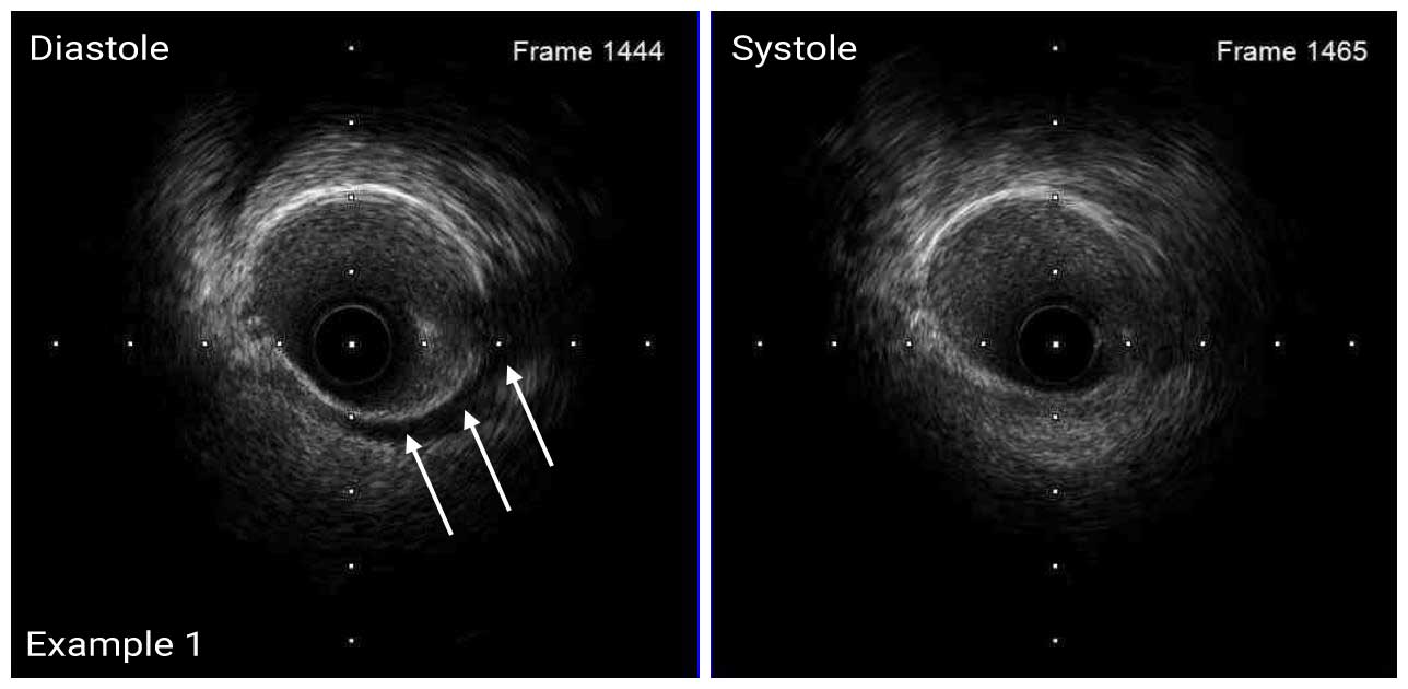
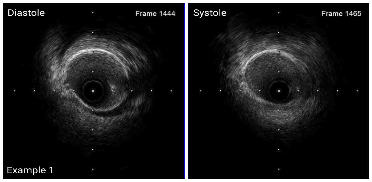
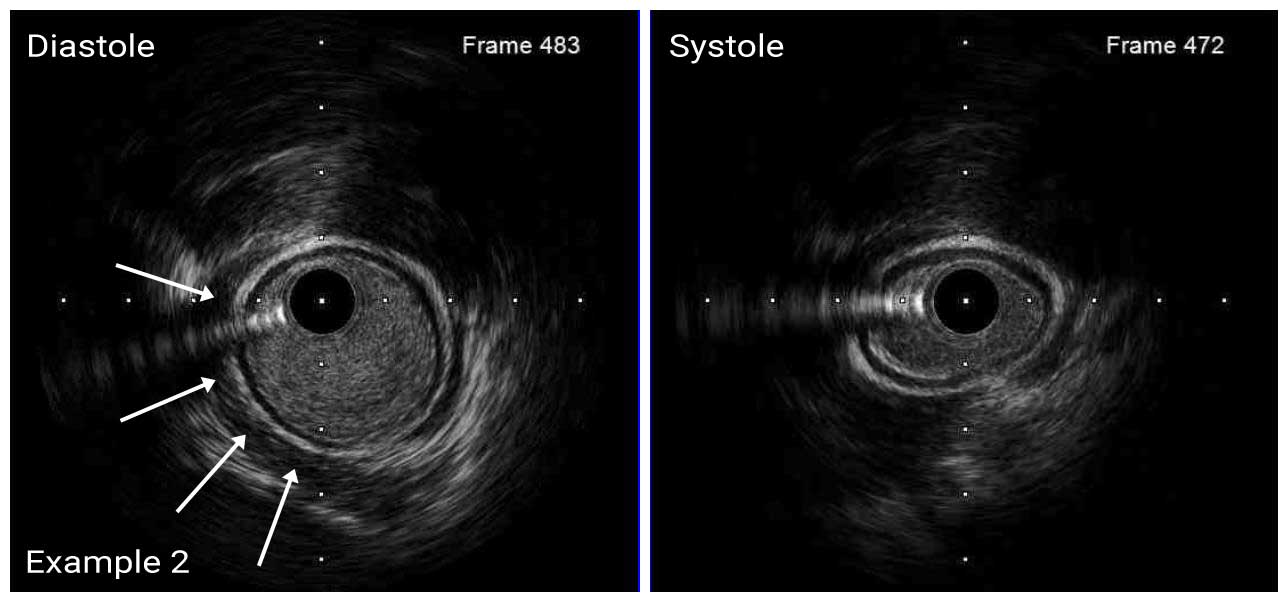
The vasa vasorum of the coronary arteries is a network of small blood vessels that supply the coronary vessel wall.¹ IVUS is able to detect vasa vasorum as a tubular, low-echoic structure at the outer side of a coronary arteries with diameter of several hundred micrometers.²

1. J Am Coll Cardiol 2011; 57: 1961-79
2. JACC Cardiovasc Interv 2013; 6: 985

Case ExamplesEducational Content

ATHERECTOMY COMPLICATIONS

Case ExamplesEducational Content

BYPASS GRAFT COMPLICATIONS

x

Left Main DK Crush Video ID

Apple
Google